0
Your Cart


Product title goes here
$19.95
Thank you! Your submission has been received!
Oops! Something went wrong while submitting the form.
There are no items in your cart. You should really do something about that.
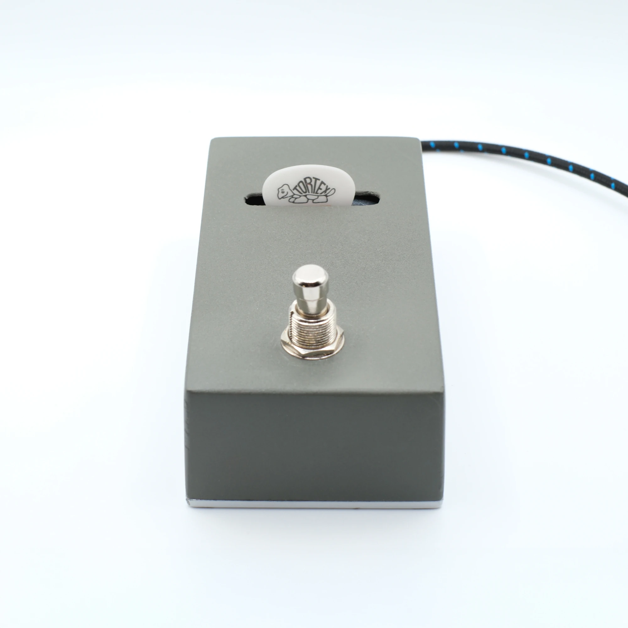
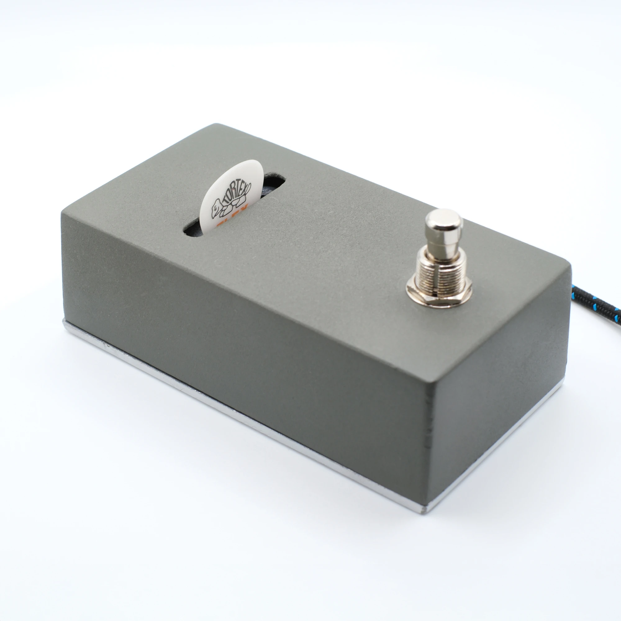
I built a pedal that dispenses guitar picks when you press the foot switch. And now you can too. Yes, I know it's a dumb idea with no utility whatsoever, but here is some context.
By no means was this an original idea. A couple of years ago, I saw a pedal company launch a Kickstarter campaign – or something like that – on a prototype of a similar kind of pedal. An interesting idea - though I’m not totally sold on the practical utility of it, being that guitar pedals are most always on the floor. And who wants to bend down to every time they need to grab a guitar pick? Eddie Van Halen used to just duct tape them to the front of his guitar. Problem solved. Brilliant, I say.
Practicality and utility aside, I was intrigued by the level of attention the company received about the pedal. Guitar World even wrote an article about it. Fast-forward to a few weeks ago and the pedal still hadn’t launched (though, in all fairness, I hear they are getting close).
So, I decided to build my own – mainly just to see if I could pull it off. Turns out that it wasn’t that hard.
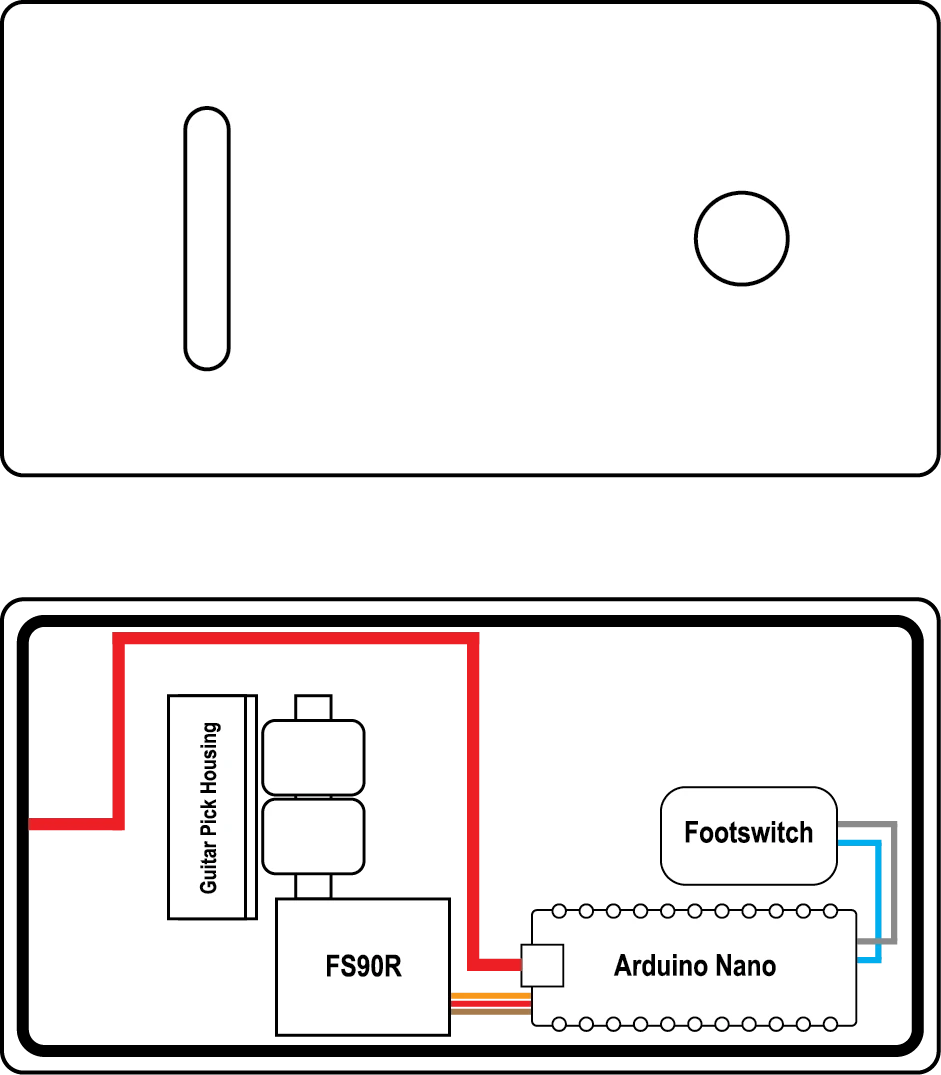
I started with a 125B enclosure. 125Bs slightly taller than 1590Bs and I needed the extra height to ensure standard sized Dunlop guitar picks could sit vertically inside the pedal. I drilled the foot switch and power port holes on the top and side, as well as the opening where the picks come out. For that, I drilled a series of adjacent holes using a 5/32 bit and used flat and round files to smooth and straighten out the edges. I then used self-etching primer to coat the enclosure and then added a couple of coats of white paint. However, by the time I had finished the pedal, the upper enclosure was pretty banged up and chipped, so I ended up sanding it down and just adding a thin layer of primer (which is why the upper enclosure is a different color from the base).
The heart of the pedal is an Arduino Nano Every circuit board and a Feetech FS90R (continuous rotation) micro servo. If you’ve never played around with an Arduino board before, don’t worry. They’re super easy (and fun) to use.
I soldered one of the foot switch (2-pronged) wires to a GND pin and the other to pin 2. The servo has three wires: red (power), brown (ground), and orange (control). Red goes to the 5V pin, brown goes to second GND pin, and orange goes to pin 9.
That’s it.
To program the Arduino board to trigger the servo for 1000ms when the foot switch is pressed, I used the following code:
#include <Servo.h>
// Pin definitions
const int buttonPin = 2; // Button connected to digital pin 2
const int servoPin = 9; // Servo connected to digital pin 9 (PWM)
// Variables
Servo myServo;
bool lastButtonState = HIGH;
bool buttonState = HIGH;
bool servoRunning = false;
unsigned long servoStartTime = 0;
const unsigned long rotationTime = 1000;
int stopValue = 1488; // Fine-tuned stop value (was 1490)
void setup() {
Serial.begin(9600);
pinMode(buttonPin, INPUT_PULLUP);
// Attach servo and immediately set to stop position
myServo.attach(servoPin);
delay(100); // Give servo time to attach
myServo.writeMicroseconds(1488); // Set to fine-tuned stop value immediately
delay(500); // Hold stop position for half second
Serial.println("=== SERVO READY ===");
Serial.println("Servo initialized and stopped.");
Serial.println("Press button to rotate for 1 second.");
// Continuously send stop signal for stability
forceServoStop();
}
void loop() {
// Read button state
buttonState = digitalRead(buttonPin);
// Check for button press (falling edge detection)
if (lastButtonState == HIGH && buttonState == LOW) {
if (!servoRunning) {
Serial.println("Button pressed! Starting 1-second rotation...");
startServoRotation();
}
delay(50); // Debouncing
}
lastButtonState = buttonState;
// Check if servo should stop
if (servoRunning && (millis() - servoStartTime >= rotationTime)) {
stopServo();
}
// Continuously reinforce stop signal when not running
if (!servoRunning) {
static unsigned long lastStopTime = 0;
if (millis() - lastStopTime > 100) { // Every 100ms
myServo.writeMicroseconds(1488);
lastStopTime = millis();
}
}
}
void startServoRotation() {
servoRunning = true;
servoStartTime = millis();
myServo.writeMicroseconds(1700); // Move forward
}
void stopServo() {
servoRunning = false;
forceServoStop();
Serial.println("1-second rotation complete!");
}
void forceServoStop() {
// Send stop signal multiple times for stability
for (int i = 0; i < 10; i++) {
myServo.writeMicroseconds(1488);
delay(10);
}
}
If I were to do this for production, I would add a separate power source for the servo (e.g., 9V battery) so that it’s not pulling from the power that’s going to the board. Any fluctuations can trigger the servo, so it’s best to keep it isolated (and solder in a capacitor and a voltage regulator in between – this would require a second small PCB board).
For the servo head, I found 3/8 inch nylon spacers at Home Depot. I drilled a small amount to widen the hole to fit over the servo tip. I then added a couple of flat rubber washers over the spacer. This is what will grab the guitar pick and push it through the top of the enclosure. You could also use rubber O-rings. I tested with both and they worked just fine.
For the housing that holds the guitar picks, I just took a Dunlop Pick Holder I bought from Guitar Center for $3.95, shaved .25” off the bottom to create a flat surface, and used epoxy to mount it onto the bottom plate of the enclosure.
Again, if I were to put this into production, I would design a more stable housing that also holds more guitar picks. I used the Dunlop because it uses a backplate with a wider diameter spring to push the picks to the front of the housing after one is pulled out. It’s a basic concept, but one that works well for this sort of project.
Mounting the servo with the head was kind of tricky and took a couple tries, but the objective is to make sure the rubber washers are pressed against the spring-loaded backplate of the pick housing so that it will properly grab the first pick and push it upward. If the servo head is press too far in, the pick will get stuck in the housing. If it’s too far away, it won’t make contact with the pick.
I also used two flat Lego squares to raise the servo about .4” above the baseplate of the enclosure so that the servo head is positioned correctly with the pick housing.
I don’t think I’ll be putting this into production or anything like that. It will take a bit more R&D to perfect – especially to accommodate different styles and sizes of guitar picks. The main hurdles would be creating a CAD drawing for the 3D-printed housing that holds the guitar picks. (and I’m a relative noob when it comes to Audodesk Fusion). Right now, this one just holds five or six picks. I’d want to design it to hold 10-12 (at a minimum). A separate 3D-printed block to accurately position and hold the servo in place is also needed.